
Building a Modern AWS DeepRacer Replacement Using Off-the-Shelf Components (Part 2)
DeepRacer Isn't Dead—It's Evolving Documenting my build of a scratch built DeepRacer car from off the shelf available parts (mostly).
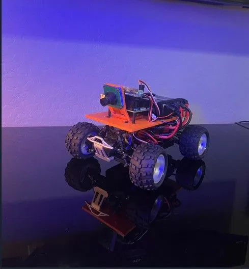
In our previous Part 1 of this article we uncovered some issues with the base RC Truck platform that needed to be corrected. We will now continue in Part 2 with the construction and assembly of our DeepRacer replacement car. If you have not read (Part 1), The link to that article is Here .
Starting where we left off in Part one we will proceed to the assembly phase of our build.
Step 6: Assembly
Let's take a step back now that I have addressed some of the shortcomings of the platform / RC truck I have chosen and cover what needs to be included in this build and how it is assembled.
6A: Prepare the Mounting Plate
6A: Prepare the Mounting Plate

3D Printed Base Plate
The first step is to 3D print the following mounting plate. This is where all of the components mount to include the camera mount, Raspberry Pi 5 and the batteries.
The next step was to drill the mounting holes in the plate. These holes need to align with the supports on the RC car that would normally be where the RC truck / car shell would mount. I measured and drilled the holes in the plate to match the position of the supports. I did this by placing the plate on top of the RC chassis to determine where the mounting holes should be. I drilled these holes so that the mounting pins on the chassis can be secured to the plate.

Bottom of Mounting Plate with all holes drilled and labeled
This being a prototype, I drilled and hot knifed the needed holes in this plate. Above is the bottom of the plate with the various needed holes. (4) holes to match up with the mounting posts on the RC Car chassis, (4) holes drilled for the mounting of the Raspberry Pi, (3) holes to mount the camera mount, and (4) slits cut to allow mounting straps for the batteries. Additionally there is one large hole for routing wires between the servo hat, the ESC and the steering servo.
6B: Assembly of the Camera and Compute Solution

Camera components: Ribbon Cable, Camera, 3D Printed Mount
Above are the components for the camera. To the left is the longer camera ribbon cable, in the center is a Raspberry Pi camera with 4 machine screws (in the mounting holes) and to the right is a 3D printed camera mount. (note the part is modified by removing a portion to make it shorter. I will update the .STL file in the near future.

Camera screwed to mount, Mount bolted to plate
Here the camera is mounted on the mounting support, and the support is mounted to the mounting plate.

Top view of camera and camera mounted. Note the 3 bolts
Here is the top view of the mounted camera mount, and the camera mounted to the plate. (The AWS badges were also 3D printed and glued to the plate for some style)

Raspberry Pi 5, Heatsink and Fan, Servo Controller Hat, GPIO Riser Spacer
Above are the components for the compute module. Top left is the heatsink and fan, Top right is the servo hat used to control the servos, Bottom left is the Raspberry Pi 5, and the connector bottom right is an extension /riser so the servo hat sits up higher and clears the heatsink and fan.

Raspberry Pi 5 Assembled with Heatsink/Fan, Servo Hat
This is the Raspberry PI 5, with the heatsink, and servo hat installed. The servo hat just mounts on top of the Raspberry PI GPIO pins, no mounting necessary.

Raspberry PI assembly with stand off supports installed

Bottom of Raspberry PI assembly with support stand offs installed
Raspberry PI 5 with 4 x supports attached for mounting to the base plate.

Raspberry PI assembly installed on base plate

Connecting the ESC and Steering Servo to the Servo Hat
Next step is to mount the plate on the car chassis. This is done with the original mounting clips that held the truck shell on the original RC car. There are 4 clips which hold the mounting posts through the holes drilled in the plate. Note that the steering servo and Electronic Speed Controller PWM cables are fed through the large hole. They will plug into the servo controller board.

PWM cable for the ESC, with the middle wire (red) de-pinned
Hardware Damage Risk: Remove and insulate the center red wire from the ESC PWM cable before connecting to servo controller. The 6V power will damage the board and possibly the Raspberry Pi. Extract the red wire, cover with heat-shrink, and connect only white (signal) and black (ground) wires. Steering servo cable needs no modification.

Heat Shrink added to de-pinned wire on ESC PWM Cable
Above is the ESC PWM cable with the de-pinned Red wire. Heat Shrink is added to the exposed pin to avoid any short circuits.

JST connector on 2 Conductor Wire - Connect Servo Hat to Custom Wire Harness
This is a small 2 conductor wire with a small JST male connector on one end and tinned wire on the other. The tinned wire ends will connect to the screw connector on the servo controller hat.

Close up of Power connection (Green) and the PWM cables installed
This is a close up of the Servo Controller Hat. At the top (green two screw connector) you will see a Red and Black wire which is the connection for power. This connects to a male JST connector that plugs into the custom wire harness. Below and left of the green power connector, labeled "0" is the ESC connector. Note the black wire goes to the left. Below the ESC connection is position "1" this is where the Steering Servo plugs in. The Brown wire will go to the left. The three connections on this board are 1. Power 2. Electronic Speed Controller 3. Steering Servo.

Custom Wire Harness
This custom wire harness is designed to deliver power to all the necessary components through (2) 7.4V chassis batteries. The two larger male Dean style connectors at the top of the picture connect to the batteries, the female Dean connector at the bottom of the picture connects to the car Electronic Speed Controller(ESC). The three small JST connectors to the left connect to: 1. The servo hat on the Raspberry Pi, 2. Voltage meter and 3. Future expansion, which could be LED lights or a cooling fan for the chassis motor.

Volt Meter - Connect a JST / 2 Wire lead to the volt Meter - Plugged into Custom Wire Harness

Custom Wire Harness connected to Car ESC, Volt Meter, and Servo Hat

Top of Car - Batteries installed
Step 7: Final Assembly
After multiple design revisions, hardware modifications, and software testing, the project finally came together.

Left Side of Car complete

Right Side of Complete Car

Front of Car Complete

Back of Car Complete
The result is a complete DeepRacer replacement built entirely from components that can still be purchased today.
No discontinued AWS hardware required.
Important
This build intentionally avoids the use of any original AWS DeepRacer hardware. Every component used in this project can be purchased new and assembled into a fully functional DeepRacer replacement platform.
References
DeepRacer on AWS:
https://docs.aws.amazon.com/solutions/deepracer-on-aws/
https://docs.aws.amazon.com/solutions/deepracer-on-aws/
Guidance for AWS DeepRacer Event Management:
https://aws.amazon.com/solutions/guidance/aws-deepracer-event-management/
https://aws.amazon.com/solutions/guidance/aws-deepracer-event-management/
Custom Car GitHub repository:
https://github.com/aws-deepracer-community/deepracer-custom-car
https://github.com/aws-deepracer-community/deepracer-custom-car
Appendix A – Bill of Materials
RC Car Chassis and Vehicle Components
| Component | Description / Purpose | Purchase Link |
|---|
| WLTOYS A979-B 1/18 Scale 4WD RC Truck | Base chassis used for the DeepRacer replacement platform | https://a.co/d/02ehTLzB |
|---|
| Aluminum Oil-Filled Shocks | Upgraded suspension to support additional vehicle weight from batteries and electronics | https://a.co/d/08ElJjnp |
|---|
| PX9200-51 Steering Servo | Standard 3-wire steering servo compatible with PWM control | https://a.co/d/0dQiRAEh |
|---|
| Hobbywing QuicRun 1060 Brushed ESC | Electronic Speed Controller compatible with Raspberry Pi PWM control | https://a.co/d/01cF0Lbv |
|---|
| Aluminum Servo Horn & Steering Linkage Kit | Required steering linkage upgrade for servo replacement | https://a.co/d/09DSjvqM |
|---|
Compute Module
| Raspberry Pi 5 (8GB) | Primary onboard computer running ROS and DeepRacer software | https://a.co/d/0iYadW1q |
|---|
| Raspberry Pi Active Cooler | Cooling solution for Raspberry Pi under sustained workloads | https://a.co/d/0fFsjYOF |
|---|
| PWM Servo Driver HAT (16 Channel) | Provides PWM outputs for steering and throttle control | https://a.co/d/0bQ9OBjQ |
|---|
| GPIO Header Riser / Extender | Provides clearance between Raspberry Pi and Servo HAT | https://a.co/d/0hVOpBtN |
|---|
| M2.5 Nylon Standoff Hardware Kit | Mounting hardware for Raspberry Pi and Servo HAT | https://a.co/d/03VdnYif |
|---|
Camera System
| Raspberry Pi Camera Module (OV5647 5MP) | Primary vision sensor for autonomous driving | https://a.co/d/02HbklfL |
|---|---|---|
| Raspberry Pi Camera Extension Cable | Extended camera cable for flexible camera mounting | https://a.co/d/0bxEg0Vk |
|---|
Power Option 1 – Dedicated Power Bank (Recommended for Simplicity)
| Component | Description / Purpose | Purchase Link |
|---|
| INIU 20,000mAh 65W USB-C Power Bank | Dedicated power source for Raspberry Pi | https://a.co/d/058lFVGU |
|---|
| Right-Angle USB-C Cable (6") | Connects Raspberry Pi to power bank while minimizing cable clutter | https://a.co/d/0iqVhNwW |
|---|
Power Option 2 – Dual Battery Configuration (Recommended for Weight Reduction)
| Component | Description / Purpose | Purchase Link |
|---|
| Zeee 2S 5000mAh 7.4V LiPo Battery | Main vehicle power source (Quantity: 2) | https://a.co/d/05Ksr6Vy |
|---|
| Deans/T-Plug Connector Kit | Used to build custom battery harness | https://a.co/d/0dAMXkgq |
|---|
| Mini JST Connector Kit | Power connections for Servo HAT and auxiliary electronics | https://a.co/d/0bQzrd0N |
|---|
| Mini Digital DC Volt Meter | Battery voltage monitoring during operation | https://a.co/d/0iW4fA76 |
|---|
| Balanced Battery Charger | Battery Charger 7.4V | https://a.co/d/0343tVMk |
|---|---|---|
| 10 Gauge Silicone Wire | Wire harness Wire | https://a.co/d/071IQEtg |
Benefits
- Reduces overall vehicle weight
- Better weight distribution
- Eliminates need for separate power bank
- Allows battery replacement without rebooting the Raspberry Pi when properly wired
Additional Requirements
- Custom wiring harness must be fabricated
- Basic soldering skills recommended
- Dual battery configuration recommended to maintain continuous power to the Raspberry Pi during battery swaps
Appendix B – Downloads
STL Files for 3D Printing / Raspberry PI build Operating System Image GitHub
3D Base Plate .STL File: https://www.thingiverse.com/thing:7376088
3D Camera Mount .STL File: https://github.com/aws-deepracer-community/deepracer-custom-car/blob/main/drawings/PiMount%20v1.2-Front.stl
GitHub Custom Car OS Image Link: https://github.com/aws-deepracer-community/deepracer-custom-car
Acknowledgements
Special thanks to Lars Lorentz Ludvigsen, David Smith, and the DeepRacer Custom Car community for providing the software foundation that made this project possible.
I would also like to recognize the many contributors helping advance the DeepRacer and DREM ecosystems: Abhishek Patil, Advait Dhamdhere, Aijun Peng, Celia Ng, Dalien Ahiekpor, Don Barber, Elmar Husmann, Joan Morgan, Ken Spokas, Nikhil Reddy, Peter DeVries, Pierre Tschirhart, Priyank Devenraj, Raul Marquez, Ryan Hayes, Sanjay Reddy Kandi, and Shu Jackson.
Additional thanks to Seyha Kry and Anthony Yimsiriwattana for testing, validation, and customer event support.
A special thank you goes to Raul Marquez for his leadership and advocacy within the DeepRacer community.
The Future of DeepRacer
This project demonstrated something larger than a hardware replacement.
DeepRacer is no longer tied to a specific piece of hardware or a managed AWS service.
Through community collaboration, open-source software, and readily available hardware, the platform continues to evolve as a powerful tool for learning reinforcement learning, robotics, and autonomous driving.
The hardware may have changed.
The learning experience remains as exciting as ever.
About the Author:
Todd Bevins has been a Technical Account Manager at AWS for 4 years and is experienced in delivering DeepRacer workshops and in person events.

Enjoyed reading this content? Let the author know!
Your likes, comments, shares, and saves help creators reach more builders.

Loading recommendations
Loading article