
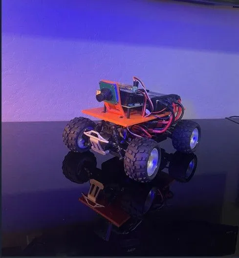
Building a Modern AWS DeepRacer Replacement Using Off-the-Shelf Components (Part 1)
DeepRacer Isn't Dead—It's Evolving Documenting my build of a scratch built DeepRacer car from off the shelf available parts (mostly).

When AWS retired the managed AWS DeepRacer service, many members of the community assumed the DeepRacer journey had come to an end.
The reality is quite different.
The DeepRacer community and AWS developers continue to innovate through open-source projects that allow customers, educators, and enthusiasts to deploy and operate DeepRacer environments within their own AWS accounts. What was once a managed AWS service is rapidly becoming a community-driven ecosystem focused on reinforcement learning, autonomous driving, and hands-on machine learning education.
I recently had the opportunity to see this firsthand during a customer event where more than 100 participants trained reinforcement learning models, deployed them, and competed in live races using the latest AWS DeepRacer solution . We also leveraged the AWS DeepRacer Event Management (DREM) solution which had become open source several years ago to manage races and leader-boards throughout the event.
The event demonstrated something important:
DeepRacer is very much alive.
In fact, many aspects of the ecosystem continue to improve through community contributions and open-source development as well as the continued development from the AWS developer team.
At the same time, another challenge has emerged.
Finding original DeepRacer hardware has become increasingly difficult. Vehicles are now primarily available through secondary markets such as eBay, Facebook Marketplace, and OfferUp. Replacement parts are becoming harder to find, and prices often exceed the original retail cost.
That raised an interesting question:
Can a complete DeepRacer replacement be built entirely from readily available parts without requiring any original AWS DeepRacer hardware?
This project set out to answer that question.
Inspiration from the DeepRacer Community
Before beginning this build, I was aware of the DeepRacer Custom Car project led by Lars Lorentz Ludvigsen and contributors within the DeepRacer community.
Their work demonstrated that the DeepRacer software stack could successfully run on alternative hardware platforms, solving many of the operating system, ROS, and software integration challenges that would otherwise require significant reverse engineering.
Their project became the software foundation for this build.
However, my goal differed in one important way.
The DeepRacer Custom Car project leveraged components from an existing DeepRacer vehicle.
My objective was to eliminate the dependency on DeepRacer hardware entirely and create a platform that anyone could build using currently available components.
Simply put:
No DeepRacer required.
Tools & Skills Required
Before committing to this build, review the tools and skills below — these are required in addition to the components listed in the Bill of Materials (BOM) in Appendix A.
Tools
- 3D printer or can be ordered from a farm (FDM; PLA or PETG recommended)
- Soldering iron (adjustable temperature, fine tip preferred / Flux and Solder)
- Drill with 3/8,15/64, 3/16, 1/16 bits
- Hot knife or heat cutter (create slots for battery hold down)
- Wire strippers and flush cutters
- Multi-meter (for continuity checks and voltage verification)
- Heat gun or lighter (for heat-shrink tubing)
- Screwdriver set (Phillips, flat and hex)
- Needle Nose Pliers
Skills
- Basic soldering (simple wire joins)
- 3D printing workflow (slicing, bed adhesion, support removal)
- Comfort with hand tools and drilling into enclosures
Estimated Total Cost
Expect to spend approximately $350–$500 on this build, depending on where you source components and whether you already own some of the parts. This estimate covers the full BOM in Appendix A.
Build Overview
This project is completed in seven steps. Estimated total build time: 3–5 hours (excluding 3D print time).
- Step 1: Selecting a Chassis — Choosing a compatible 4-wheel drive platform / chassis
- Step 2: Designing a New Platform — 3D printing a custom mounting plate (I have created the .STL file for car.
- Step 3: Replacing the Electronics — Swapping the ESC and steering servo for PWM-compatible components
- Step 4: Power System Design — Configuring power for the Raspberry Pi and chassis
- Step 5: Upgrading the Suspension — Installing stiffer shocks to handle the added weight
- Step 6: Assembly — Mounting all components and wiring the system
- Step 7: Completed Build— Verifying the completed build
Step 1: Selecting a Chassis
After researching the original DeepRacer platform, I discovered that the WLTOYS A979-based chassis is the same chassis used for the original DeepRacer cars. The primary difference is the original DeepRacer car had a steel plate with mounting buses that is used to mount the DeepRacer compute module. Aside from this difference, the chassis was the same as RC cars or so I thought.

WLTOYS RC Truck

RC Truck

WLTOYS A949 Chassis all stock conponents
Stock WLTOYS A949 RC Truck- Note the chassis is the same used in the DeepRacer car with only minor differences.
The platform offered:
- Independent suspension
- Four-wheel drive
- Brushed Electric motor
- Same 1/18th scale chassis as the original DeepRacer
- Widely available replacement parts
Most importantly, it could still be purchased new.
Initially, I expected the conversion to be relatively straightforward.
That assumption changed as soon as I started examining the factory electronics.
Step 2: Designing a New Platform
Because I wasn't reusing any original DeepRacer components, I need to source a way to mount:
- Single-board computer
- Camera
- Servo controller
- RC Car Chassis
- Vehicle batteries
- Wiring and supporting electronics
I started by creating a custom 3D-printed mounting platform specifically designed for the WLTOYS A949 chassis.

3D Printed Component Mounting Plate
Note: The holes were drilled after printing; however, an updated version of this .STL file will be made available to match the end result. I wanted to show the process / journey to create the working part.

RC Car Chassis with Component Mounting Plate
Note: The holes in the mounting plate match the upright mounting usually used for the shell.
The first iteration of the plate was to validate the size and shape to ensure everything would fit / mount. Note too that I used a drill and hot knife to create mounting holes and slots for Velcro as the build progressed.
Factors in this design:
- Weight distribution / Battery placement
- Wire harness
- Ease of assembly / Off the shelf parts (with the exception of the 3D printed parts)
- Long-term serviceability
The final result is a repeatable mounting platform that anyone with a 3D printer can reproduce.
Step 3: Replacing the Electronics
The biggest challenge turned out to be the stock RC electronics.
The RC Truck purchased for this project includes an integrated receiver and electronic speed controller (ESC). This differs from the DeepRacer car as the ESC used does not include an integrated RC receiver. While this works well for traditional RC driving, it creates significant challenges when attempting autonomous control.

Close up of Stock Electronic Speed Controler (ESC) which must be replaced
The integrated design of the ESC does not expose a standard PWM control interface (3 conductor JST Plug) that can be directly connected to the servo controller. This necessitated the replacement of the ESC with one that has a PWM wire to connect to the servo hat to allow the Raspberry Pi to control the speed controller.
The steering system introduced a second problem.
The factory steering servo used a proprietary four-wire connection instead of the standard three-wire interface used by most hobby servos.

Stock RC Truck Servo PWM Wire - Note the proprietary connector and 4 conductors.
The above picture is the 4 pin wire cable from the stock steering servo that connects to the combination ESC / RC Receiver. The plug is not the standard size and also not the standard 3 wire needed for the servo hat and controller.
This meant neither the ESC nor the steering servo could be directly integrated into the DeepRacer build by plugging into the servo controler planned for this build. To solve these issues, both components had to be replaced.
ESC Replacement
The factory receiver and ESC assembly was removed and replaced with a standard ESC capable of connecting to the servo hat, which is installed on the Raspberry Pi. To remove and replace the stock ESC, it is simply a matter of prying it out as it is double back taped in. The new ESC is installed in the same way and comes with the tape for installation.
Replacement ESC - Stock ESC lacks the wire to connect to the Raspberry Pi GPIOs. This ESC is similar to what is in the stock DeepRacer car. It has the 3 pin PWM cable needed to connect to the servo hat board on the Raspberry Pi 5.

New Replacement Electronic Speed Controller (ESC)
Servo Replacement
The steering servo was replaced with a standard three-wire servo compatible with common hobby electronics.
This required replacing portions of the steering linkage and installing upgraded metal steering components.

New Replacement Servo - 3 wire PWM cable
Note: The control horn is too wide that comes with the servo. I replaced it with a narrow aluminum control horn.
While these upgrades added steps and expense, they replaced proprietary ESC and servo with standard PWM compatible components, allowing the vehicle to be connected to the servo controller. Optimally I would have liked an RC car that had a compatible ESC and servo. This adds cost to the build, but the replacement parts are quality and work well. I will update this article if I find a better RC car that requires less modification.
Step 4: Power System Design
One of the most important design decisions in any custom DeepRacer build is how to power the onboard computer.
During development, I experimented with two different approaches.
Option 1: Dedicated Power Bank for Compute / Separate battery (7.4V) for the Car Chassis.
The simplest solution is to power the onboard computer using a dedicated USB-C power bank and power the car chassis separately via 7.4V S2 battery. This is how the original DeepRacer is configured. By splitting up the compute power from the chassis power, it provides an advantage in that the chassis batteries can be swapped out during an event without rebooting the compute unit. This reduces the down time by not having to reboot and reconnect the compute unit every time a battery is changed.
For this build, I selected a 20,000mAh INIU 65W power bank capable of supplying sufficient power (5V 4 Amp) while providing excellent runtime; sufficient to keep the compute unit running for an entire day of racing.

20000mAh Power Bank used to power the Raspberry Pi 5 (Option 1)
Advantages:
- Simple installation (USB-C to USB-C cable to Raspberry Pi 5)
- No custom wiring
- Excellent runtime
- Battery separate from Car Chassis Battery – Pi stays running when swapping chassis batteries
Disadvantages:
- Additional weight
- Occupies mounting space
- Higher center of gravity
For builders seeking the fastest path to a working vehicle, this is the easiest option.
Option 2: Powering Through the Chassis Batteries
A second approach is to power the Raspberry Pi 5 directly through the servo hat using the vehicle batteries which are 7.4V 2S.
This approach eliminates the need for a dedicated power bank and reduces overall vehicle weight.
However, it requires building a custom power harness.

Custom Wire Harness Diagram

Customer Wire Harness Components
Above are the components to create a custom harness: This includes wire, connectors and the volt meter.
- 3 x male and female Mini JST connectors
- Connect the harness to the servo hat
- Connect to the optional voltage meter
- Future expansion to run LED lights on the front of the car.
- There are also two male and one female Dean T connectors
- 2 x Male connectors to connect to two 7.4V 2S batteries
- 1 x Female to connect to the car ESC.
- Solder
- Flux
- Heat Shrink

Completed Custom Wire Harness
Above is the completed harness and wire diagram. The bottom connector connects to the car electronic speed controller (ESC), the top two connectors connect to (2) 7.4V 2S batteries. The three mini JST connectors connect to 1. Servo hat / power for the Pi, 2. Voltage Meter, 3, Future expansion to LED lights to indicate when the chassis is powered on or cooling fan for the motor.
The custom harness routes power from the chassis batteries into the servo hat, which then powers the onboard computer.
Advantages:
- Lower overall weight, even when running two batteries.
- Improved weight distribution / lower center of gravity
- Cleaner installation
- Fewer components
Disadvantages:
- Custom wiring required
- More complex assembly
- Soldering skills needed.
Battery Redundancy
One lesson learned during testing was the importance of maintaining uninterrupted power to the onboard computer.
If power is lost from swapping out batteries, the computer must reboot before the vehicle can operate again.
To address this issue, I recommend using two 7.4V 2S batteries within the vehicle power system.
This allows one battery to be disconnected and replaced while maintaining power to the computer.

2 x 7.4V 6000mAh batteries connected to the custom wire harness
Above we have the custom wire harness plugged into (2) 6000mAh 2S 7.4V batteries. The connector on the far left gets connected to the car ESC. The voltage meter plugs into one of the 3 JST connectors at the bottom of the picture, and the meter will get mounted on the back of the car. It indicates the health of the batteries and gives an easy way to determine if the batteries need to be changed. The other JST connectors will be used (1) to power the Raspberry Pi / servo hat, and the 3rd is for future expansion. The two batteries are connected to the two male Dean connectors to the right. The advantage of having two batteries is each can be swapped independently, maintaining power to the Raspberry Pi. If only a single battery was used, it would necessitate rebooting the Raspberry Pi each time batteries need to be swapped. In a DeepRacer event it is common to need to swap the chassis batteries throughout the day.
Comparing Both Designs
Configuration A
- (1) chassis battery (Powering the car 7.4V 2S Battery)
- (1) 20,000mAh power bank 5V 4 Amp (Powers the Raspberry Pi and servo hat)

Option 1 for power: 1- Power Bank and 1-7.4V 2S Chassis Battery
Configuration B
- (2) 7.4V 2S Batteries which power both the car chassis and the Raspberry Pi and servo hat.
- Custom power harness
- No power bank

Option B - Custom Harness, 2 x 7.4V 2S Batteries No Power Bank
Above is the custom DeepRacer car with (2) 6000mAh batteries connected to the car via a custom wire harness. Notice the voltmeter mounted on the back of the car (hot glue for now)
Builders looking for simplicity will likely prefer the power bank approach as no custom harness needs to be built.
Builders seeking the lightest possible vehicle may prefer the no power bank configuration. The wire harness is not complicated but adds some expense to the build and requires some soldering skills to assemble. Also with a custom harness, the voltmeter is a helpful option for the build.
Step 5: Upgrading the Suspension
After the car was assembled, another challenge emerged.
Weight / Suspension compression
The completed scratch-built vehicle carries a significant amount of weight in the batteries. The shocks used by the RC truck for the build have softer shocks than the stock DeepRacer car. The shocks need to be replaced with heavy duty shocks to support the weight of this build. While this is adding steps to the build and expense, it is needed.

Stock RC Truck Shocks Compressed.
Above is the assembled vehicle with the stock shocks / RC chassis. Note: The suspension is nearly 100% compressed.
Compared to the original DeepRacer, the stock shocks feel noticeably softer under load.
I purchased and installed upgraded shocks to correct this issue. Otherwise the wheels would rub on the 3D printed mounting plate.

New Replacement Shocks - Can support more weight
These are the replacement shocks with much stiffer springs that can handle the weight far better than the stock shocks.

New Shocks Installed
New shocks are installed. Almost no compression under load.
The RC Truck selected is the same chassis used for the DeepRacer car, however I discovered a few items which needed alteration:
- Electronic Speed Controller (ESC) The RC truck indeed had an ESC, however it was a combined RC Receiver, and ESC. Because of the integrated nature, it lacked the PWM cable to connect to our servo hat for the Raspberry Pi. The ESC we swapped it out with is a simple ESC and has the PWM cable.
- Steering Servo The servo that came with the truck was made to work with the integrated ESC. The PWM cable has a 4-wire configuration with a mini connector. The servo swapped this out for has the standard 3 wire PWM cable. Also needed was to purchase a smaller control horn, as the one the servo came with was too wide.
- Shocks which came with the RC truck were too soft and would not support the weight of the larger batteries. These were swapped out for stiffer shocks which support the weight.
Now that we have addressed the major issues with the RC Truck platform we will convert into a fully functional DeepRacer car, we will continue in Part (2) of this article with the assembly and construction of the vehicle.
Part(2) of this article can be found Here
Enjoyed reading this content? Let the author know!
Your likes, comments, shares, and saves help creators reach more builders.

Loading recommendations
Loading article