

Scale-Driven Architecture: Lessons from a Hyperscale Multi-Tenant Agent Platform on EKS - Part 2: Isolation and Storage Trade-offs
Part 2 explores two decisions that quotas alone can't answer: VM-level tenant isolation with Kata Containers (bare metal, Graviton, nested virt — each with its own cost profile), and the four storage paths on EKS (EBS, async S3, EFS, S3 Files), each running into a different ceiling at 100k+ pod density.

Part 2 — Trust and Persistence: Isolation and Storage Trade-offs
A three-part series. Part 2 of 3.
Part 1 covered the capacity layer — networking and pod density. Both are problems with numbers attached: IPs per VPC, pods per node, prefixes per subnet.
Part 2 is about two decisions where the numbers don't tell you the answer.
The first is isolation. Every tenant runs in its own pod, but a pod is not a strong boundary — a kernel bug or a container escape reaches the host. Whether that matters depends on your threat model, not your quota sheet. Kata Containers shows up as the path to add a VM boundary per tenant.
The second is storage. Each tenant accumulates state — conversation history, retrieved context, tool outputs. Where that state lives decides what failures the tenant sees. Four storage paths are common on EKS, and each runs into a different ceiling at 100k+ pod density.
Neither of these is a permanent choice. Kata's overhead, EFS's scaling behavior, and the alternatives around both are all moving fast enough that the answer in a year or two probably looks different. The design goal isn't to pick a winner — it's to keep the exit cost low.
Why Pods Aren't a Trust Boundary
In a single-tenant cluster, a pod is a fine unit of isolation. Namespaces, cgroups, seccomp, and AppArmor keep one workload from stepping on another, and that's usually enough when everyone running on the cluster belongs to the same organization.
Multi-tenant is different. Every pod on a node shares the same kernel. A kernel CVE, a side-channel on shared CPU state, or a container escape doesn't stop at the pod boundary — it reaches the host, and from the host every other tenant on that node. The security model is only as strong as the kernel, and the kernel is a large attack surface shared across tenants who don't trust each other.
The standard answer to this is VM-level isolation: give each pod its own kernel, so a compromise stops at the guest. Kata Containers is the mature way to do that on Kubernetes — each pod runs inside its own lightweight VM, transparent to the workload, managed by a CRI runtime.
VM-level isolation isn't free, though, and at 100k+ tenant density the cost math is unforgiving. The rest of this section walks the paths to get there and what each of them costs.
The Paths to VM-Level Isolation
There are three paths to running Kata on EKS today. All three run Kata successfully; each one comes with its own cost profile — pricing, configuration, or tooling.
x86 bare metal (
c7i.metal and similar). The most straightforward path — Kata's tooling targets x86 first, runtime compatibility is the cleanest here, and there is nothing exotic to configure. The cost is pricing: metal instances are the only option — there is no shared-tenancy SKU — and the per-pod cost at hyperscale density runs well above the shared-kernel baseline.Graviton bare metal (arm64). Graviton offers a cheaper price-performance profile than x86 for many workloads, so a Graviton metal SKU (
c7g.metal, m7g.metal) is a natural direction to consider. Kata does run — KVM is available natively — but arm64's virtualization path has an ACPI limitation: QEMU's virt machine type, the only arm64 option, doesn't support runtime CPU hotplug (the GIC requires all CPU redistributors at boot). The workaround is a Kata configuration flag, static_sandbox_resource_mgmt = true , which makes Kata read the pod's resources.limits.cpu at VM start and allocate all vCPUs upfront. It has one user-facing implication: pods must declare a CPU limit (or they get the default 1 vCPU), and CPU can't be resized after VM boot. For a fixed-per-tenant CPU allocation model, that's a tradeoff, not a blocker.x86 nested VM (
c8i / m8i / r8i). In February 2026 AWS enabled nested virtualization on non-metal EC2 instances , initially on the 8th-generation Intel families c8i, m8i, and r8i. Nested virt under Kata works on self-managed c8i nodes; the open piece is autoscaler-driven provisioning. Karpenter doesn't currently know how to provision nodes with nested virtualization enabled, so anything past a static node group loses on-demand scaling. Karpenter PR #9043 adds support; once it merges, this path removes the bare-metal tax on the whole exercise.The costs themselves are also moving: metal pricing shifts over time, the Karpenter PR is active, and Kata's arm64 configuration knob is stable enough that it's already documented as the canonical fix. When any of these moves, the shared-kernel-to-Kata migration is a configuration change, not a research project.
Firecracker and gVisor
Two names that come up in the same conversation as Kata, worth brief notes.
Firecracker. The lightest of the Kata-supported hypervisors, but host filesystem sharing is a hard constraint against it in this design. The Mountpoint for S3 CSI driver — the canonical way to expose S3 buckets as POSIX paths to Kubernetes pods — mounts on the host through FUSE and bind-mounts the result into the pod. In a microVM runtime, getting that host mount visible inside the guest requires a virtiofs device. Firecracker doesn't ship one: the VirtioFS device backend PR was closed for attack-surface reasons, and there is no supported path for Kubernetes-native host filesystem sharing into the guest. QEMU and Cloud Hypervisor both support virtiofs — this is a Kata hypervisor choice, not a Kata-wide constraint.
gVisor. A user-space syscall interceptor rather than a VM — lighter runtime overhead, weaker isolation boundary. For this platform's threat model, that's not enough.
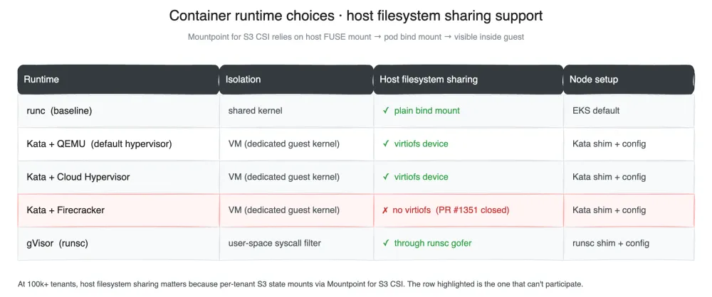
Container Runtime Choices
The Constraints on Tenant Storage
Each tenant in this platform runs its own pod with its own state — conversation history, retrieved context, tool outputs, per-tenant configuration. OpenClaw itself is local-first: configuration and agent memory are written to the pod's local filesystem. Shared storage doesn't sit on the hot path; it carries per-tenant persistence that needs to survive pod restarts, reschedules, and node replacement.
That framing matters, because it means storage selection at this scale isn't primarily a performance decision. It's a decision about semantics and operational surface: what consistency guarantees does the tenant see, and how much of the storage machinery does the application have to reimplement? Throughput and latency matter, but they aren't what picks the path.
The density constraint from Part 1 still applies. At 100k+ tenant density with hundreds of pods packed onto each node, any storage path that doesn't fan out cleanly per pod is ruled out before the semantics discussion even starts.
Four Paths, Their Failure Modes
There are four common paths to attach per-tenant persistent storage on EKS today. All four are in use at some scale across the AWS ecosystem. Under the 100k+ density and pod-per-tenant shape, each one hits a different failure mode.
EBS. The obvious starting point — a block device per tenant, attached to the node hosting the pod. EBS doesn't make it past density. Each EC2 instance has an EBS volume attachment limit set at the instance level, and the numbers are well below a hyperscale pod density target. An
m8a.16xlarge allows 48 EBS volume attachments ; m8a.24xlarge allows 64, and the only way to reach triple digits is m8a.48xlarge at 128. Part 1's pod density target was 200+ pods per node. The per-tenant-volume model is off by roughly an order of magnitude at any instance size a cost-conscious cluster would pick.S3 async sync family.
aws s3 sync as a sidecar, or one of the FUSE-like layers in the same family — JuiceFS, Alluxio, and similar projects that buffer writes locally and reconcile to S3 on an interval. Two problems, both structural. First, durability has a window: any write that happens between sync cycles is lost if the pod crashes before the next reconcile. Whether that window is 10 seconds or 5 minutes, it exists, and tenant state is exactly the kind of data where a small loss window is hard to reason about. Second, the sync logic is the application's problem: failure modes, retries, conflict resolution, shutdown flushing — all of it gets pushed into the application layer, which doesn't want to own a storage system.EFS. NFSv4 with close-to-open consistency : once a client closes a file, subsequent opens on any other client see the written state, and the data is durable. Compared to the async-sync family, the loss window collapses from "one sync interval" to "between write and close" — and the application can control that boundary explicitly with
fsync. EFS carries three specific scaling walls that any deployment past six-figure tenant counts will meet; the next section walks them.S3 Files. Generally available in April 2026 , after this platform's storage design was already in place. S3 Files is built on EFS technology and presents an S3 bucket as an NFS-mountable file system. It's worth naming as a natural evolution over EFS: writes go through a file system interface and S3 Files handles the bucket-side reconciliation — an application-level simplification over the sidecar pattern. On the scaling side, it inherits EFS's per-file-system and per-account quotas, so the walls discussed in the next section apply equally to an S3 Files deployment at this density.
EFS at Scale: Three Walls
EFS has the right semantics. At 100k+ tenant density it also has three specific scaling walls, each at a different layer of the stack.
Wall 1: Access Points per file system. EFS access points are the primary per-tenant isolation primitive — each tenant gets its own AP with its own POSIX identity and root directory. The per-file-system cap was 1,000 historically, which forced 100+ file systems just to cover a six-figure tenant count. In February 2025 the limit rose to 10,000 — a 10× improvement. It doesn't eliminate the problem.
At 100k+ tenants, a single file system can't hold the fleet. That means sharding tenants across file systems — and sharding across managed EFS file systems is a harder problem than sharding across, say, DynamoDB tables, because EFS file systems are heavier objects with their own lifecycle and quota footprint (the second EFS-side limit worth naming: 1,000 file systems per account per region , a soft quota raised only through AWS Support case-by-case review — meaning once you're multi-filesystem by necessity, the second ceiling isn't a hard API return code but a support process).
The questions this forces on the platform are the standard multi-tenant sharding questions, but they all land above the managed boundary and have to be answered by the platform:
- Placement. When a new tenant provisions, which file system does the AP get created on? By AP count? By stored capacity? By tenant-ID hash? Each option has different hot-shard behavior.
- Registry. Something has to remember which file system each tenant's AP lives on — authoritative, queryable by both the provisioning path and the mount path. At this scale it's a data store, not a convention.
- Capacity planning. File systems have to be created ahead of demand, because creating one on the critical path of a tenant-provision request means racing a slow control-plane API against a user-visible latency budget.
- Rebalancing. When a shard fills or gets hot, moving tenants between file systems means copying the access point's data across file systems — closer to a migration than a pointer update, because the data is in the file system, not behind it.
Wall 1 sits above the managed boundary. The next one sits on the client side of it.
Wall 2: CSI driver version tracking. The AWS-side lift to 10,000 didn't automatically reach every client. The EFS CSI driver held an internal cap of 1,000 access points per file system until PR #1806 raised it to match AWS, shipped in v2.3.1 . Until the driver upgrade landed, the effective ceiling for a cluster was still 1,000 regardless of the service-side number. The practical takeaway is a diagnostic one: when a managed-service limit moves, every client library, driver, and controller in the path has its own version and its own effective limit, which have to be tracked independently.
Wall 3: Provisioning speed. Dynamic provisioning — creating an EFS access point on demand when a new tenant's PVC is bound — doesn't keep up with scale-up rate. The underlying EFS control-plane API throttles, and the CSI driver serializes against it, so at bring-up the provisioning step becomes the critical path. The fix isn't faster provisioning; it's decoupling. Access points are pre-created in bulk into a pool, and the tenant lifecycle is decoupled from the access-point lifecycle entirely. Creating a tenant becomes an O(1) claim against the pool instead of a synchronous call into a throttled API, and releasing a tenant returns the AP for reuse or cleanup out-of-band. This pattern generalizes to any managed-service API whose provisioning rate lags behind the workload's scale rate.
Two Patterns from the Storage Layer
Two patterns fall out of this that apply well beyond EFS.
Managed-service limits stack through layers. A limit lifted at the service API isn't a limit lifted for you. Every layer between the service and the application — driver, controller, client library, application config — can hold its own independent cap, and the effective limit is the minimum across all of them. When a managed-service limit moves, the diagnostic isn't "can we use the new number"; it's "which layer in the stack is the bottleneck now." The EFS CSI driver's 1,000 hardcode sitting behind AWS's 10,000 lift is the clean example, but the shape shows up everywhere managed services are composed with client-side tooling.
Slow provisioning APIs call for decoupled pools. When a managed-service API's provisioning rate can't keep up with the workload's scale rate, direct dependency on that API in the request path becomes a startup-time tax. Decoupling the resource lifecycle from the consumer lifecycle — pre-provisioning resources into a pool, making consumer creation an O(1) claim — turns a synchronous throttled call into a background-amortized one. The pattern is generic: it works for EFS access points, it works for IAM roles, it works for any provisioning API whose rate is a constant while the workload's demand is a spike.
What These Two Decisions Taught Us
Every path has a cited constraint. In both the isolation and storage sections, no path was ruled out by preference. Each one is anchored to a specific external fact: a hardware limitation, an open pull request, a quota value in a documentation page, a line in a release note. When any of those facts move, the decision moves with them. That is what makes this kind of architecture auditable at all — six months from now, the analysis can be re-run without having to reconstruct why the old answer was the old answer.
The design goal is keeping exit cost low, not picking winners. The intro said it, and both sections bear it out. The shared-kernel baseline works today, and the Kata exploration is what keeps the migration cheap when it stops working. EFS works today, and the operational patterns (sharding above the managed boundary, pooled provisioning) are the ones that port to S3 Files or whatever the next evolution looks like. At this density, none of the current answers will be the final answer, and designing as if they were is how platforms end up with migrations that look like rewrites. The first takeaway makes decisions traceable; this one keeps them movable.
Parts 1 and 2 framed the cluster at rest. Part 3 is about the cluster in motion: how long it takes to bring 100k+ tenants into existence on a cold cluster, why that latency is measured in hours and not minutes, and why the reasons are their own set of stacking ceilings — scheduler throughput, etcd size, IAM association caps.
Enjoyed reading this content? Let the author know!
Your likes, comments, shares, and saves help creators reach more builders.

Loading recommendations
Loading article